- The paper introduces a bimanual robotic system that mimics human harvesting by coordinating a camera arm for stem unveiling and a grasping arm for crop manipulation.
- The method uses advanced point cloud processing and velocity control to optimize camera centering and obstacle avoidance, ensuring precise stem pre-cut positioning.
- Experimental evaluations with UR5e arms validate the approach, demonstrating successful stem exposure and force-controlled crop manipulation in lab setups.
Bimanual Crop Manipulation for Robotic Harvesting
This paper introduces a bimanual robotic system designed for harvesting crops, specifically addressing the challenges posed by sensitive crops and cluttered environments, such as vineyards. The core contribution is a dual-arm coordinated motion control methodology that enables the robot to reach a stem pre-cut state, mimicking the actions of human harvesters.
The system consists of two robotic arms: a grasping arm with Ng degrees of freedom (DOF) for securing and manipulating the crop, and a camera arm with Nc DOF equipped with an RGB-D camera and a cutting tool. The camera arm's task is to approach the stem while maximizing its visibility, whereas the grasping arm manipulates the crop to create space for the cutting tool. The control objectives are:
- Camera Arm:
- Reaching and centering within a region of interest (ROI) surrounding the stem.
- Unveiling the stem by maximizing the number of visible points from the stem's point cloud.
- Grasping Arm:
- Maximizing free space around the stem to facilitate cutter placement by applying force position control.
Proposed Control Methodology
The control methodology involves a velocity-controlled bimanual robot, where the reference velocity control signal Vr is designed to coordinate the motion of both arms. The approach relies heavily on processing the scene's point cloud to estimate critical point positions and identify obstacles.
Scene Point Cloud Processing
The point cloud data is processed to classify points into several subsets (Figure 1):
- W: Whole scene point cloud.
- S: Stem point cloud.
- T: Top cluster of the stem point cloud.
- B: Bottom cluster of the stem point cloud.
- O: Obstacle point cloud.
- Opr: Projected obstacle point cloud.
- F: Free-space point cloud.
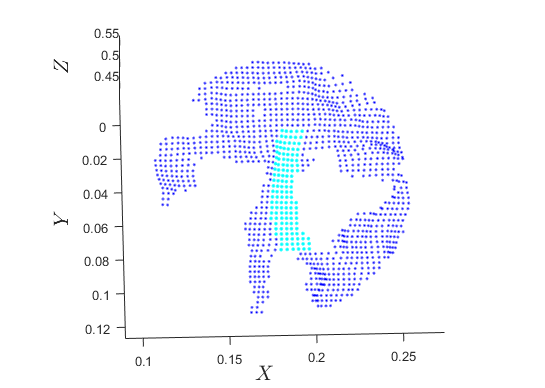
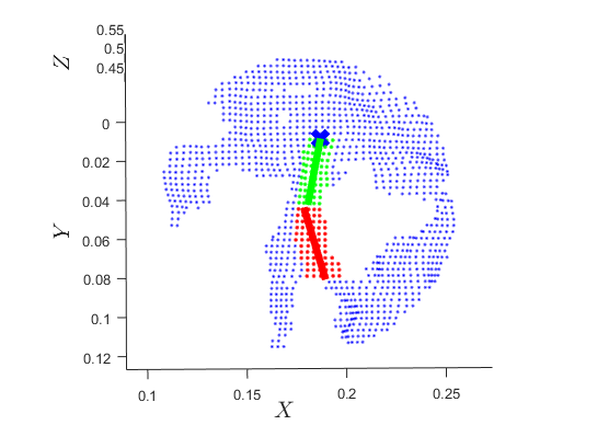
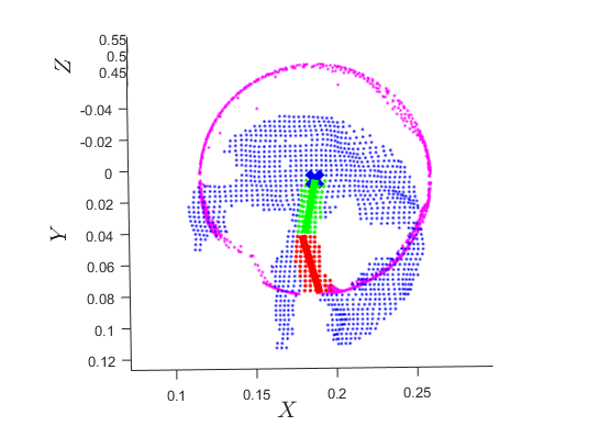
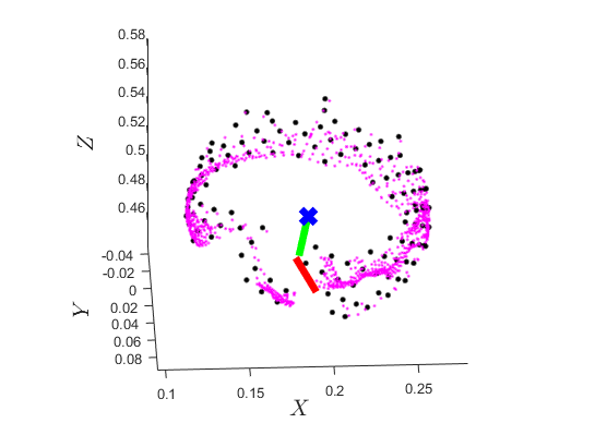
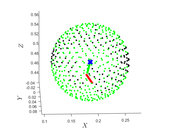
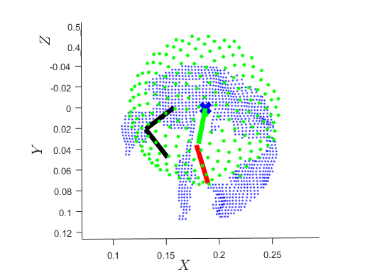
Figure 1: Scene's point-cloud W containing an obstacle subset O and stem subset S.
The stem's base psb is estimated using PCA on the clustered stem point cloud. Obstacles are identified within a sphere centered at psb. Free space F is determined by projecting obstacle points onto a sphere and sampling the sphere's surface using the Fibonacci lattice methodology. The point pgd is then calculated by solving an optimization problem to maximize the distance from surrounding obstacles.
Camera Arm Control
The camera arm's end-effector reference velocity Vc is a superposition of two control signals:
- Reaching Reference Velocity Vcr: Achieves reaching and centering by converging the camera position pc to a manifold Ω and aligning the camera's Z axis with the ROI center.
- Unveiling Reference Velocity Vcu: Maximizes the visible part of the OOI using a barrier artificial potential field around each obstacle, inducing a virtual repulsive velocity uj,k that rotates the camera to increase visibility.
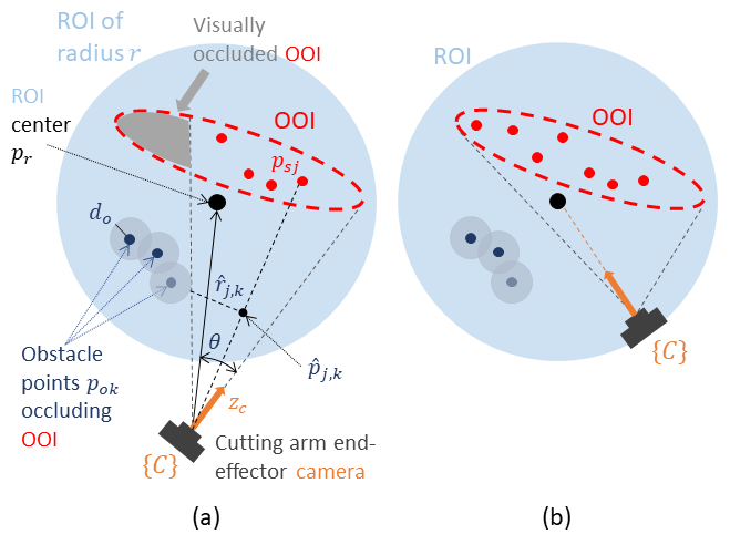
Figure 2: Camera arm control methodology visualizing the initial state and the desired state.
Grasping Arm Control
The grasping arm's reference velocity Vg is designed as a force/position controller:
- A position control signal vp minimizes the position error projected onto the space orthogonal to nc.
- A force control signal vf applies force along nc to stretch the stem.
- An orientation control signal vgω aligns the arm's end-effector with the stretched stem.
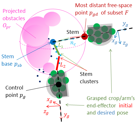
Figure 3: Grasping arm force/position and orientation control where force control is applied at nc, position control is applied at subspace I3×3−ncnc⊺, and orientation control aligns nc with yg.
Bimanual Motion Scheduling
The camera arm initiates the reaching/unveiling motion, and once certain thresholds are met, the grasping arm's motion is activated. The grasping arm's translational velocity is superimposed onto the camera arm's reference velocity to assist in avoiding stem occlusions.
Experimental Results
The proposed method was evaluated in a lab setup using two UR5e robotic arms, a RealSense D415 camera, and a mock-up vine with a plastic grape cluster (Figure 4).
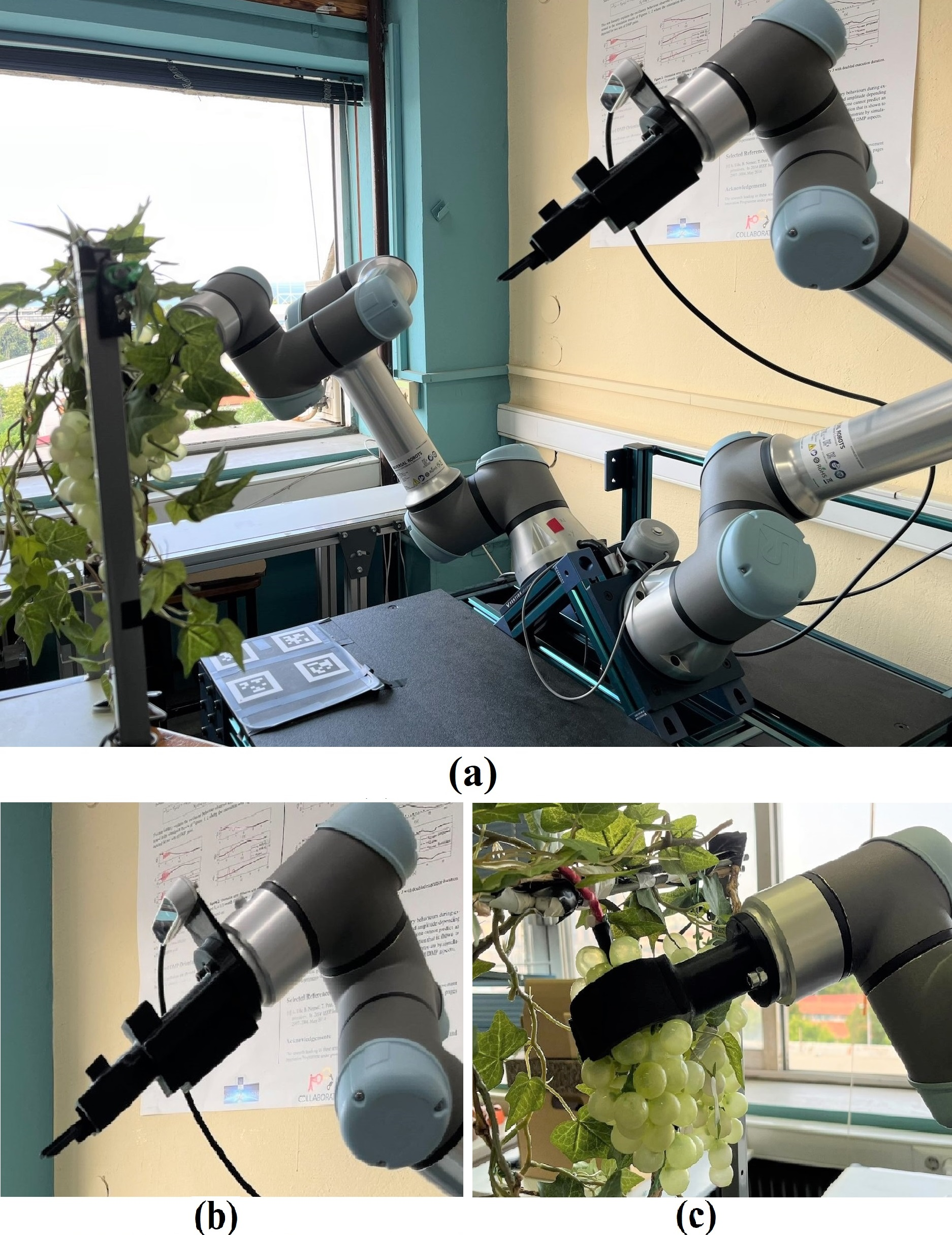
Figure 4: (a) Lab setup, (b) Camera arm, (c) Grasping arm initial state.
Experimental results demonstrate successful reaching and centering (Figure 5), stem unveiling (Figure 6), and force/position control by the grasping arm (Figures 8, 9).
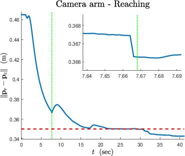
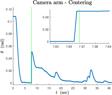
Figure 5: Reaching with desired region radius r = 0.35 m shown as a red dashed line.
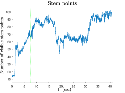
Figure 6: Unveiling of visible stem points with respect to the camera.

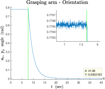
Figure 7: Position error.
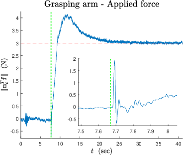
Figure 8: Applied force with desired force magnitude fd shown as a red dashed line.
The in-hand camera's viewpoint at different stages of the process illustrates the stem's unveiling and the creation of cutting affordances (Figure 9).
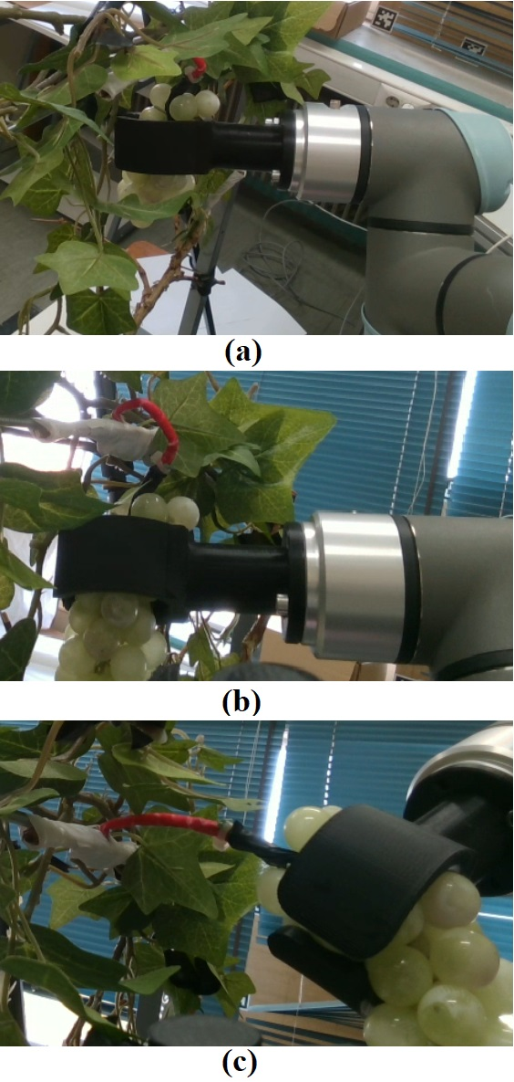
Figure 9: In-hand camera's viewpoint at the process start, bimanual motion's start, and end of the overall task.
Conclusion
The bimanual control methodology effectively enables a robot to reach a pre-cut state for crop stems by coordinating the motions of a camera arm and a grasping arm. Future work involves testing the proposed method in a real-world vineyard environment.