- The paper presents TelecomTM, a novel system that employs pre-existing fiber-optic cables as virtual sensors for accurate vehicle detection and characterization.
- It integrates system characterization and spatial-domain Bayesian filtering to manage sensor heterogeneity and complex noise conditions in vehicle tracking.
- Real-world tests demonstrate its effectiveness with a 90.18% detection accuracy and significant improvements in vehicle position and speed estimations.
This paper introduces TelecomTM, a system designed for fine-grained and ubiquitous traffic monitoring using pre-existing telecommunication fiber-optic cables as virtual strain sensors. The system leverages vehicle-induced ground vibrations to detect, track, and characterize individual vehicles. The key components of TelecomTM include a system characterization module and a Bayesian analysis module that addresses challenges related to unknown sensor properties and complex noise conditions. The system shows high accuracy in real-world evaluations, demonstrating its potential for cost-effective and low-maintenance traffic monitoring.
Physical Foundations and System Overview
The foundation of TelecomTM lies in distributed acoustic sensing (DAS) technology, specifically Phase Sensitive Optical Time Domain Reflectometry (ϕ-OTDR) (Figure 1). The system exploits the principle that vehicle motion induces unique vibration patterns on the ground, which are then transmitted to roadside telecom fiber conduits. The system uses these vibrations, which contain information about vehicle characteristics, to monitor traffic and infer vehicle activities with fine-grained spatial resolution. TelecomTM consists of two main modules: a System Characterization module, which estimates the geographic location and analyzes the signal pattern of each virtual sensor, and a Bayesian Analysis module, which detects, tracks, and characterizes vehicles based on the sensor data (Figure 2).
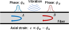
Figure 1: Illustration of the principle of DAS. A strain perturbation affecting the optical fiber caused by vibrations between A and B produces linearly proportional variations in the phase of the backscattered light.
System Characterization Module
The System Characterization module addresses the challenges posed by unknown and heterogeneous properties of virtual sensors. It involves driving tests using a car equipped with a GPS antenna to estimate the geographic position of each virtual sensor. This is achieved by matching the vehicle's GPS signals with the induced telecom fiber responses.
Signal Pattern Analysis
The system analyzes the signal patterns of telecom fiber responses, which can vary significantly due to factors such as cable spooling and near-surface heterogeneity (Figure 3). These variations necessitate different methods and model parameters for accurate vehicle detection. The system identifies two primary signal patterns: bell-shaped and polarity-flipped responses (Figure 4). For bell-shaped responses, vehicle motion creates a peak that is detected at local maximums, while for polarity-flipped responses, vehicle motion creates a valley that is detected at local minimums. The system also estimates the transmissibility of each virtual sensor, defined as the ratio between the prominence amplitude of the quasi-static signal and the testing vehicle weight.
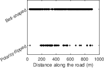
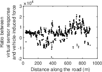
Figure 3: Spatial-variations of telecom fiber signal characteristics: (a) signal pattern and (b) transmissibility (ratio between virtual sensor response and vehicle's weight). Signal properties of distributed virtual sensors have large spatial variations.
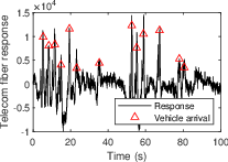
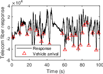
Figure 4: Telecom fiber signal examples of (a) bell-shaped and (b) polarity-flipped response. Red triangle markers indicate arrival times of vehicles. Vehicles are detected at local maximums for the bell-shaped response and at local minimums for the polarity-flipped response.
Bayesian Analysis Module
The Bayesian Analysis module is designed to address the challenges posed by large and complex noise conditions. It employs a three-step approach: per-sensor detection, spatial-domain Bayesian filtering and smoothing, and vehicle characterization.
Spatial-Domain Bayesian Filtering and Smoothing
The spatial-domain Bayesian filtering and smoothing algorithm integrates spatially dependent information across adjacent virtual sensors to reduce false positive detections and estimate vehicle motion states (positions and speeds) (Figure 5). This algorithm estimates the posterior probability of vehicle arrival time recursively over space, fusing spatial-dependent vehicle detection results across multiple virtual sensors.
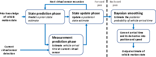
Figure 5: Our Bayesian filtering and smoothing algorithm.
Vehicle Characterization
TelecomTM estimates vehicle wheelbase lengths and weights using vehicle speed estimations and the quasi-static component of the vehicle-induced signals (Figure 6). Wheelbase length is estimated using the high-frequency telecom fiber response created by a vehicle's wheels passing over bumps or joints in the road. The time difference between the two wheel-induced responses is estimated using the auto-correlation function, and the wheelbase length is calculated by multiplying this time difference by the vehicle speed. Vehicle weight is estimated by computing the weighted average of quasi-static signal prominence, assuming a linear relationship between prominence amplitude and vehicle weight (Figure 7).
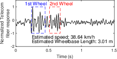
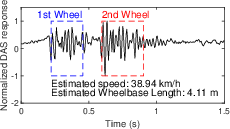
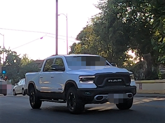
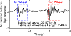
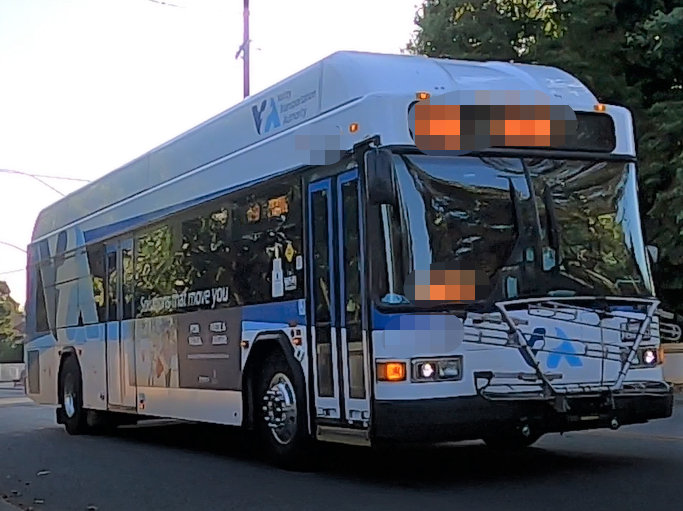
Figure 6: High-frequency responses (geq3 Hz) and the estimated wheelbase lengths of (a) a sedan, (b) a pickup truck, and (c) a bus. Our system estimates wheelbase length by estimating the vehicle speed and time difference between the wheel-induced vibration responses.
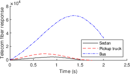
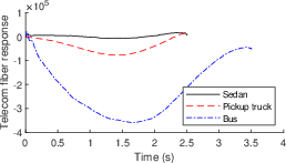
Figure 7: Quasi-static signals of (a) bell-shaped and (b) polarity-flipped responses for three different types of vehicle. Heavier vehicle creates larger prominence amplitude.
Experimental Evaluation and Results
The TelecomTM system was evaluated through comprehensive field experiments on a 900-meter road with regular traffic (Figure 8, Figure 9). The system achieved a 90.18\% two-way traffic detection accuracy, 27× and 5× error rate reductions for vehicle position and speed tracking, respectively, compared to a baseline method without geo-localization. Wheelbase and weight estimations had errors of ±3.92\% and ±11.98\%, respectively (Figure 10, Figure 11, Figure 12, Figure 13).
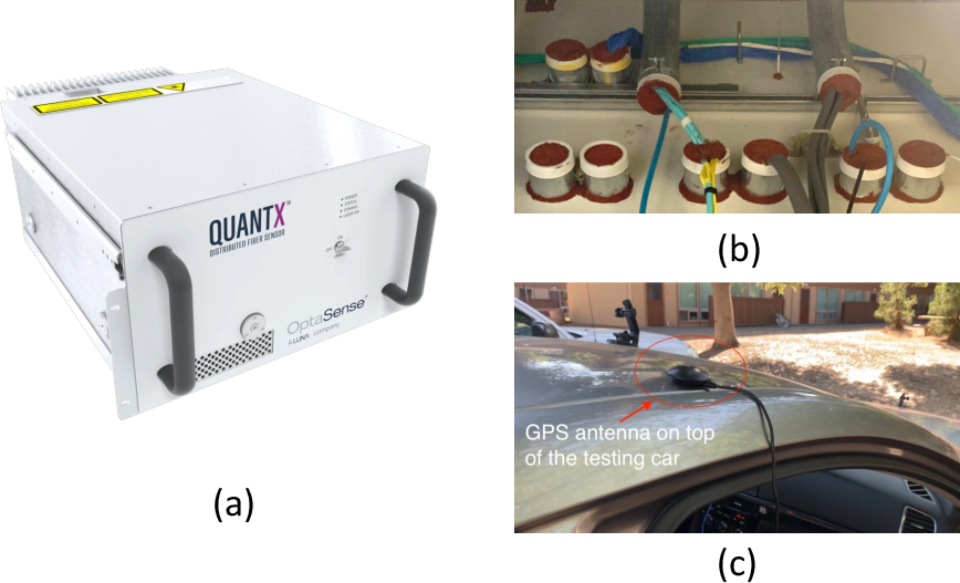
Figure 8: Experimental setup: (a) the QUANTX interrogator~\cite{quantx}
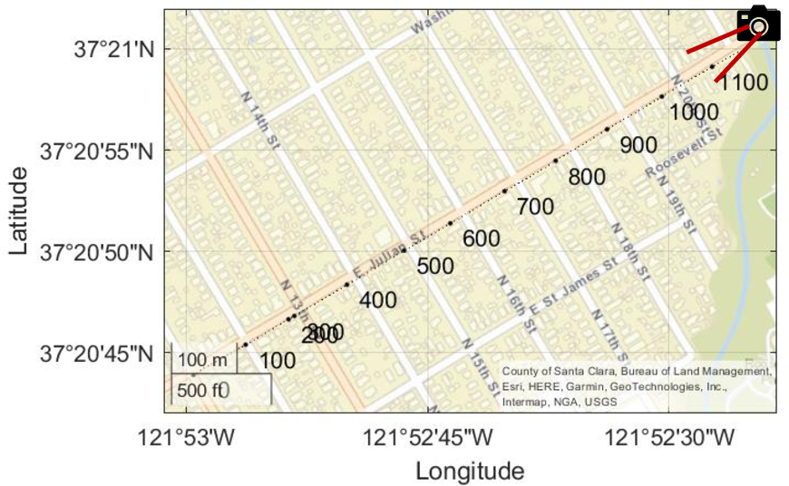
Figure 9: Locations of virtual sensors. The camera icon indicates the location of a camera. The dot line and numbers indicate virtual sensors' locations
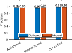
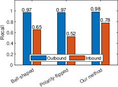
Figure 10: (a) Precision and (b) recall of detection results using only bell-shaped responses, polarity-flipped responses, or using our method with all distributed sensors. Our method improves vehicle detection recall by fusing spatial dependency information from distributed virtual sensors.
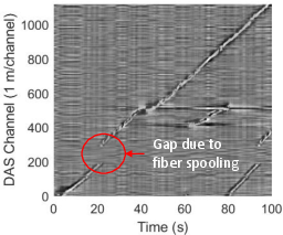
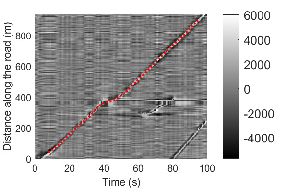
Figure 11: Telecom fiber response with the y-axis being (a) the fiber distance to virtual sensors or (b) the distance along the road after geo-localization. Red dot curve in (b) shows our vehicle tracking result. Our method removed the signal gap (red circle) due to fiber spooling and estimated the geographic locations of virtual sensors by matching the testing vehicle signal and the corresponding telecom fiber response.
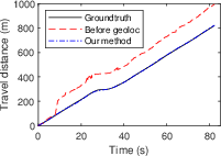
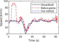
Figure 12: Vehicle (a) locations and (b) speeds ground truth (black curve) and estimations before (blue curve) and after (red curve) geo-localization (geoloc).
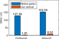
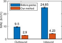
Figure 13: {Mean absolute value bar chart with a 95\% confidence interval} for vehicle (a) location and (b) speed estimations before and after geo-localization (geoloc). {The number above each bar indicates the mean absolute value.} Our method improves the vehicle location and speed estimation accuracy by geo-localizing each virtual sensor.
Effects of Sensing Distance and Vehicle Type
The system's performance was characterized by examining the effects of sensing distance, vehicle types, crosstalking events, and vehicle moving speed. Vehicle-induced vibrations attenuate as the distance between the vehicle and the fiber cable increases, leading to reduced accuracy in detecting vehicles farther from the cable. Larger vehicles tend to produce stronger signals, resulting in better detection accuracy (Figure 14).
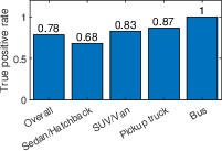
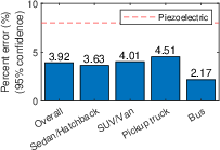
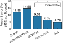
Figure 14: Effect of vehicle types. (a) shows the true positive rate (TPR) of vehicle detection for different vehicle types. The larger the size of a vehicle, the better the vehicle detection result. (b) and (c) show the percent error (95\% confidence interval) for wheelbase and vehicle weight estimations. Red dash lines indicate the percent error of current commercial piezoelectric sensors.
Crosstalking and Channel Spacing
Crosstalking events, where signals from multiple vehicles overlap, can negatively impact detection performance, particularly for vehicles farther from the fiber cable (Figure 15). The study also examined the effect of DAS channel spacing, finding that vehicle tracking error increases as channel spacing increases (Figure 16).
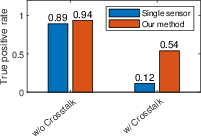
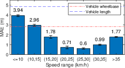
Figure 15: Effect of crosstalking events. True positive rate of vehicle detection with or without crosstalking using a single sensor or our method with distributed sensors.
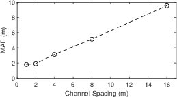
Figure 16: Effect of channel spacing. Multiple vehicle tracking. Mean absolute errors of vehicle location estimation with different channel spacing values.
Conclusion
The TelecomTM system presents a viable solution for fine-grained and ubiquitous traffic monitoring using pre-existing telecom fiber cables. By addressing the challenges of unknown sensor properties and complex noise conditions through system characterization and Bayesian analysis, TelecomTM achieves high accuracy in vehicle detection, tracking, and characterization. Future research directions include understanding environmental influences, characterizing noise and uncertainties, and exploring complex roadway configurations to generalize TelecomTM to a wider range of conditions.