- The paper introduces an anchor-free UWB radar system that achieves sub-decimetric obstacle mapping on mobile robots.
- It employs a three-stage signal processing pipeline—including target identification, adaptive filtering, and DBSCAN clustering—to enhance detection accuracy.
- Experimental results demonstrate high precision and low localization errors, enabling robust SLAM in challenging, visibility-impaired scenarios.
Infrastructure-Free UWB Radar for Obstacle Detection and Mapping on Mobile Robots
Introduction and Motivation
The presented paper introduces a robust, infrastructure-free methodology for obstacle detection and environment mapping using ultra-wideband (UWB) radar integrated on a mobile robotic platform (2512.01018). Existing prevalent solutions—such as RGB cameras and LiDAR—suffer major limitations in low-visibility scenarios due to adverse lighting, smoke, fog, or reflective surfaces. UWB radar, with its wide bandwidth and short pulse characteristics, provides strong penetration capabilities and resilience to such conditions, while also enabling sub-decimetric range resolution. Unlike traditional UWB localization systems that require anchor-tag infrastructure, this approach operates entirely without fixed anchors, rendering it suitable for both structured and dynamic unknown environments.
UWB Radar Signal Characteristics and Sensing Challenges
UWB systems transmit ultra-short (sub-nanosecond) pulses spanning several GHz, with typical operation between 3.1 GHz and 10.6 GHz. The resulting channel impulse response (CIR) contains a direct line-of-sight (LoS) component followed by temporally separated multipath reflections, each corresponding to environmental features or objects.
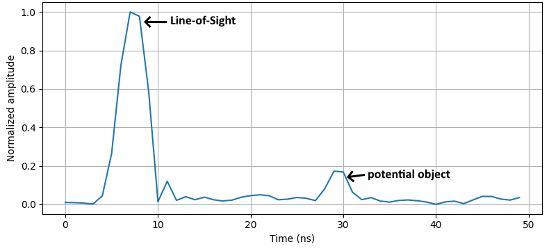
Figure 1: Example of a Channel Impulse Response where the object is placed at a distance of 3.5 m.
The CIR’s multi-peak structure enables precise discrimination of close-proximity reflectors. However, dynamic, cluttered, or anchor-less settings introduce prominent noise and multipath, complicating target extraction. Different obstacle materials (e.g., metal, concrete, and plywood) exhibit distinct reflection amplitudes and temporal characteristics in CIR, necessitating material-adaptive peak identification and noise filtering.
Processing Pipeline: Peak Detection to Environment Mapping
The paper's core contribution is a signal processing pipeline partitioned into three stages:
- Target Identification utilizes amplitude/phase processing of CIRs from multiple antennas to extract candidate reflection peaks, leveraging both preamble and STS-based CIRs for accurate time-of-flight and phase-difference estimates.
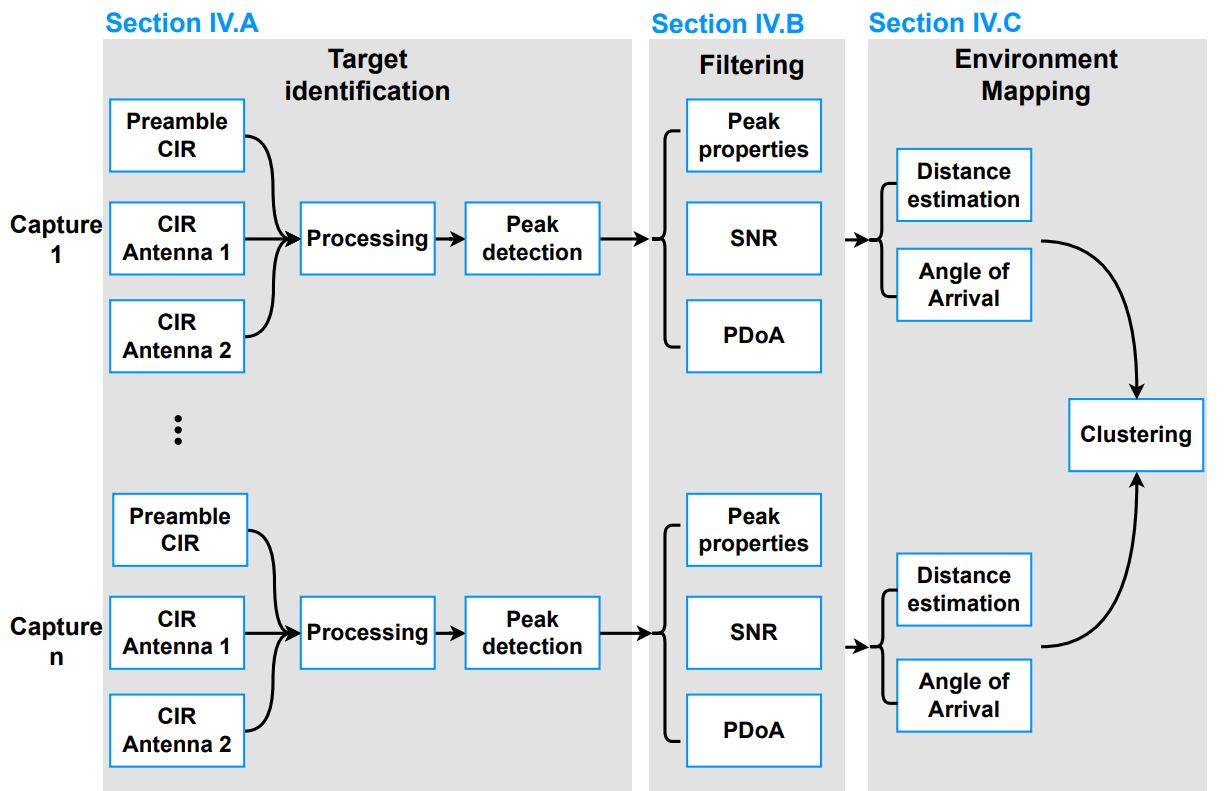
Figure 2: Overview of the proposed approach—sequential processing of CIRs to estimate distance, angle-of-arrival, and cluster object reflections.
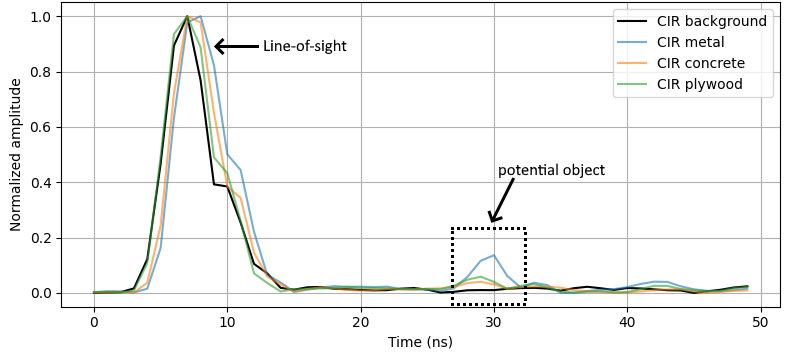
Figure 3: Overlaid CIRs for metal, concrete, and plywood objects highlighting differential reflectivity and peak characteristics.
- Filtering exploits four main criteria—peak width, prominence, signal-to-noise (SNR) score, and phase-difference-of-arrival (PDoA). Parameter tuning is data-driven: e.g., for metal, prominence thresholds can be higher than for low-reflectivity plywood.
- Filtering based on SNR compensates for increased attenuation with distance.
- PDoA-based angle-of-arrival (AoA) estimation restricts admissible peaks to those within the reliable angular field of view.
- Clustering and Mapping aggregates multiple sequential observations into spatial clusters using DBSCAN, grouping consistent points and eliminating isolated multipath noise.
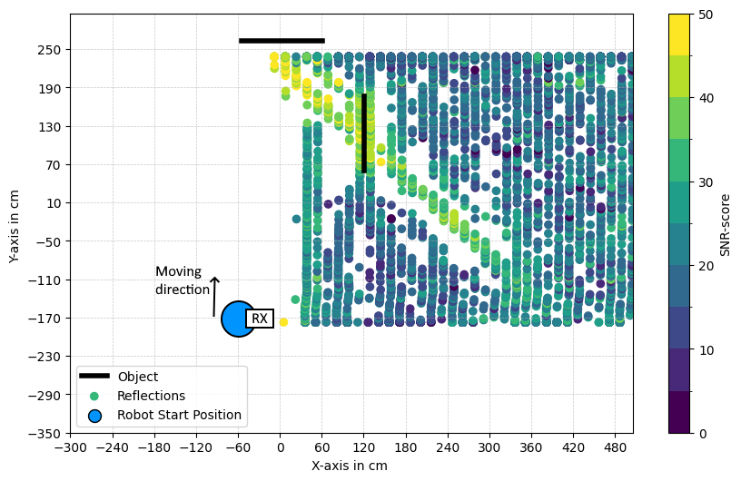
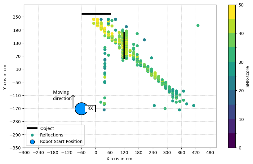
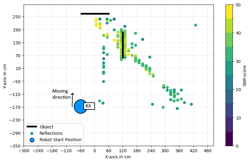
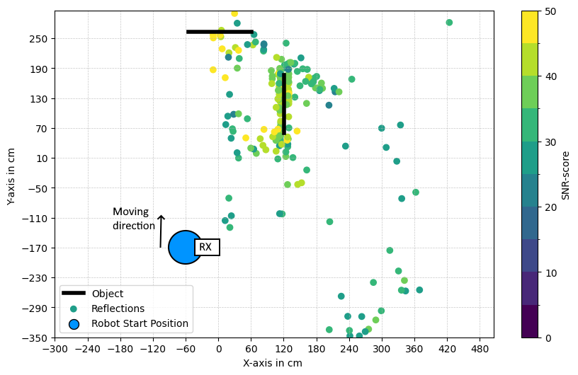
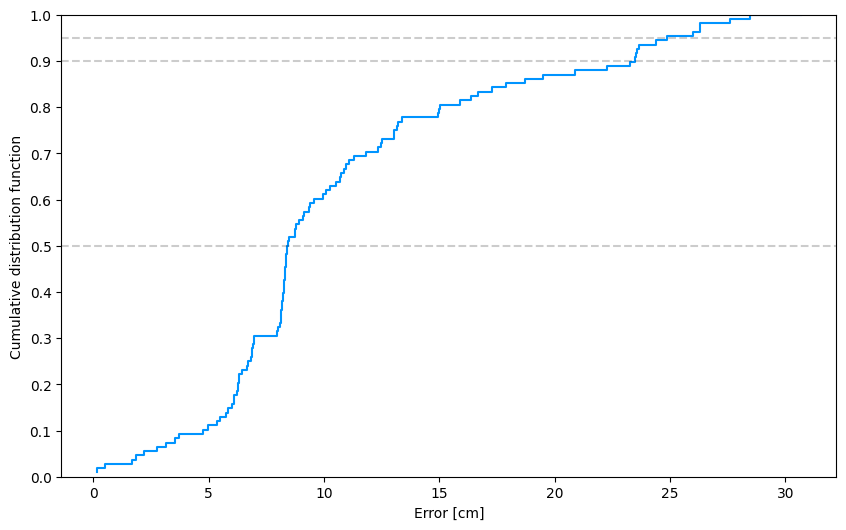
Figure 4: Effects of successive pipeline stages illustrated on point cloud: raw reflections, width/prominence/SNR filtering, PDoA filtering, positional calculation, and final clustering.
Experimental Setup and Data Acquisition
A TurtleBot 4 platform was equipped with an omnidirectional UWB transmitter and four dual-antenna directional receivers, compliant with IEEE 802.15.4 (QM33120W sensor, channels 5 and 9, 500 MHz bandwidth). The robot operated in an IIoT lab with ground-truth motion capture.
Different objects—metal plates, concrete, and plywood boxes—were positioned, and data collected as the robot moved linearly or in the presence of multiple reflectors.
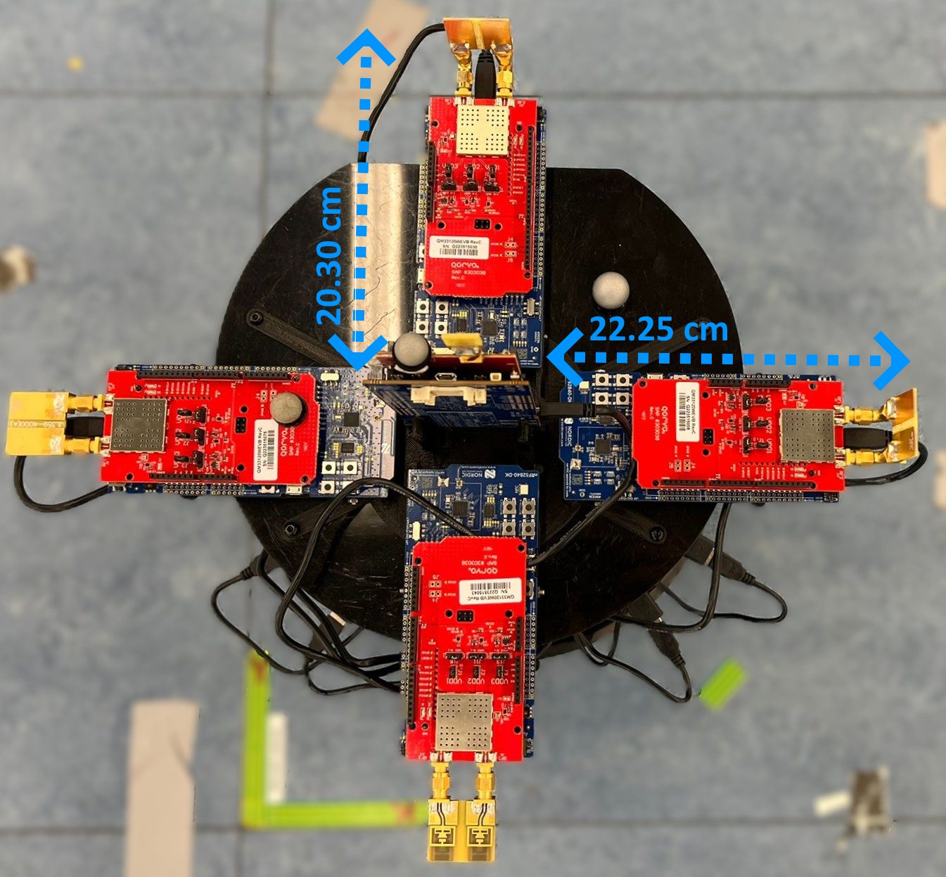
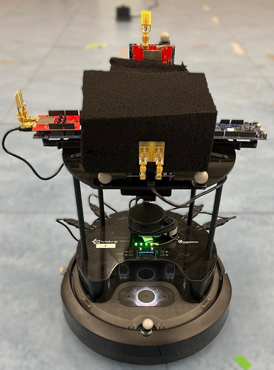
Figure 5: a) Antenna placement on TurtleBot 4; b) Front view with antennas and absorber.
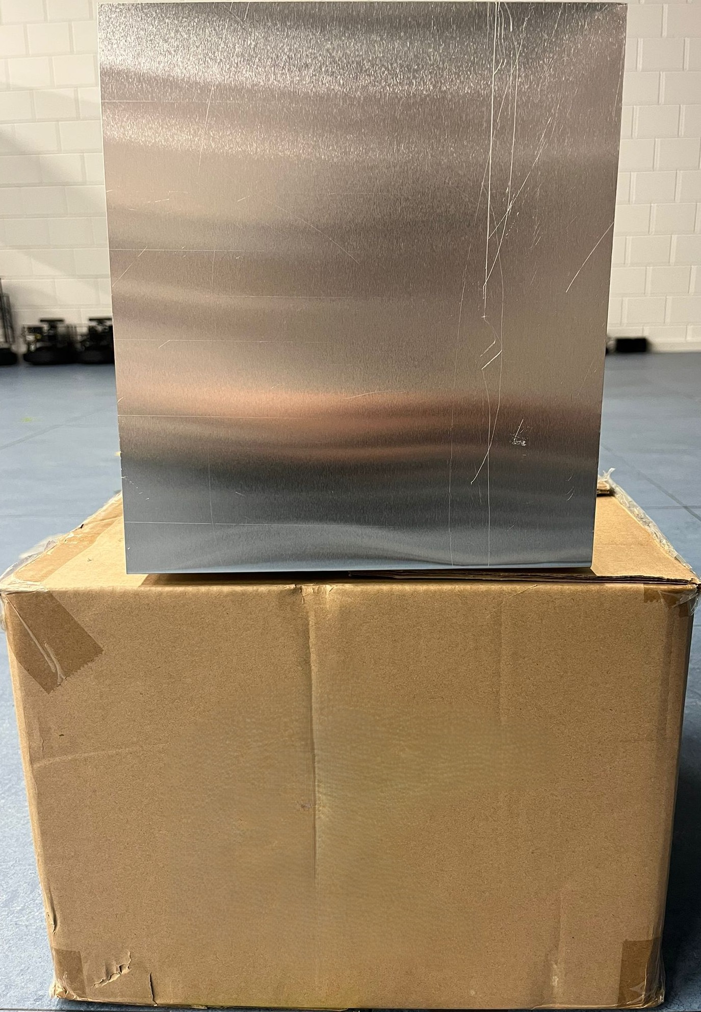
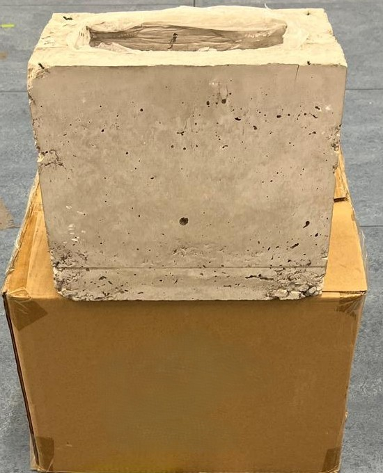
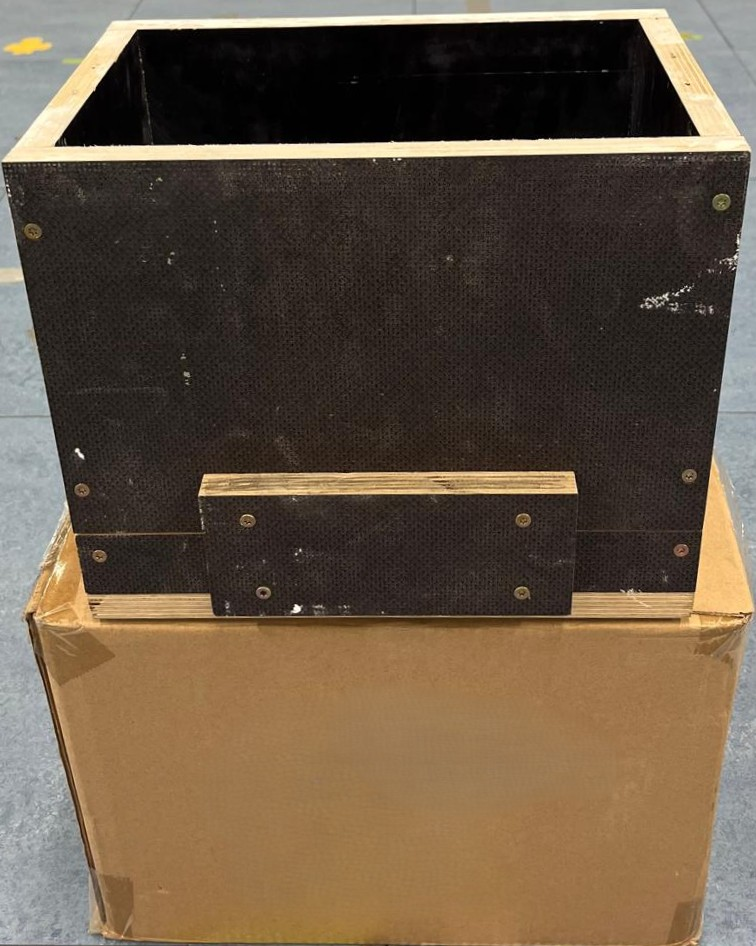
Figure 6: a) Metal plate; b) Concrete box; c) Plywood box—target objects for assessing material-dependent detectability.
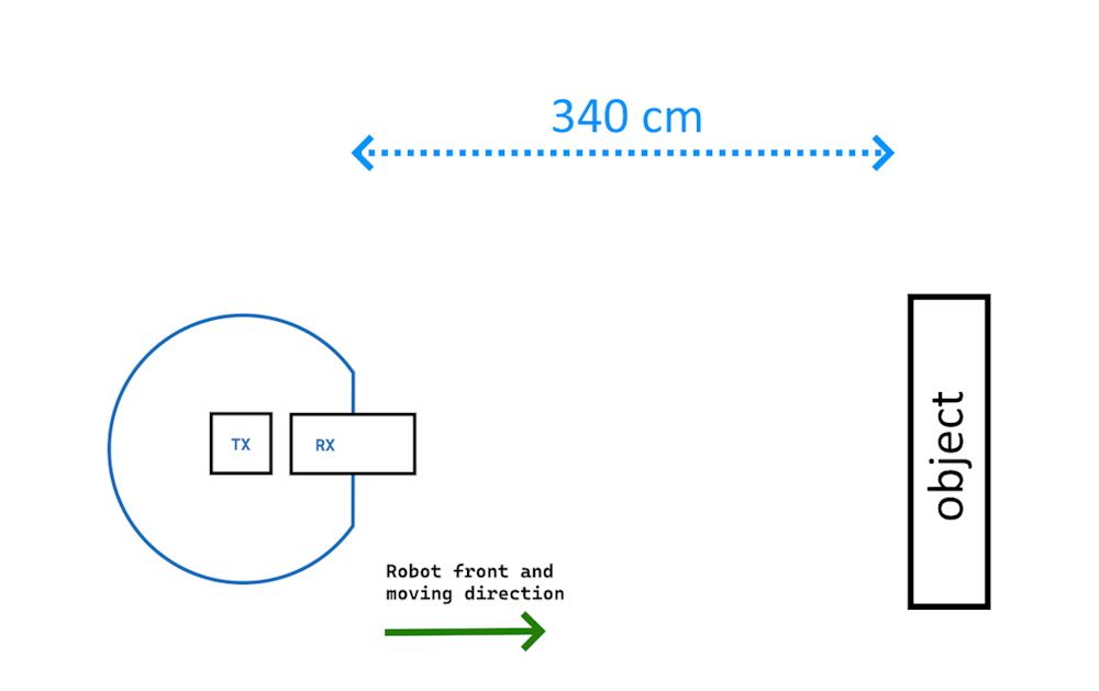
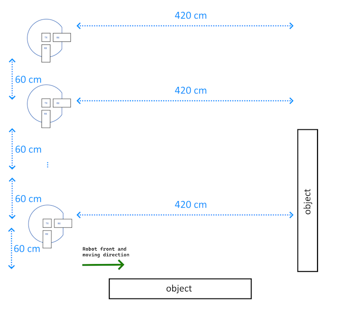
Figure 7: a) Robot approaches single object for each material; b) Two-object test with challenging multipath.
Empirical Evaluation
Peak Property Analysis
Analysis showed that with increasing distance, the detected peak prominence in CIRs decreases while width increases, irrespective of material.
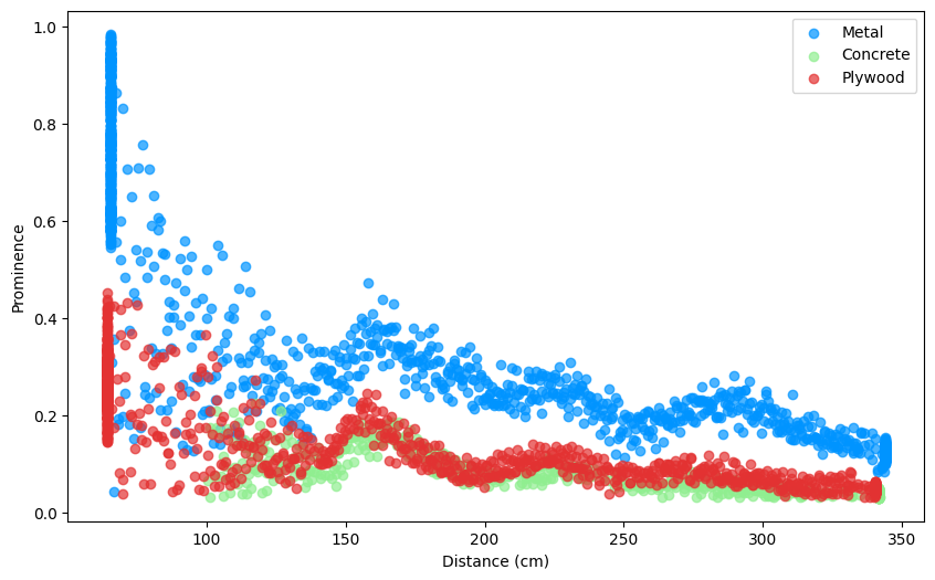
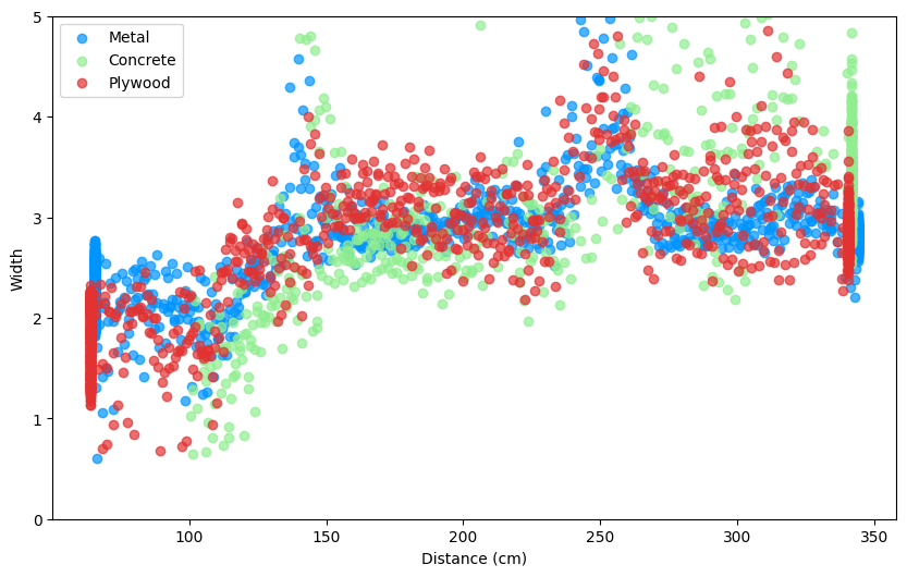
Figure 8: a) Prominence vs distance: rapid decrease for all materials b) Width vs distance: increase with range for all.
Optimal filtering parameters (width, prominence, SNR-score) are material and channel-dependent; e.g., metal peaks are more separated from the noise floor than plywood.
The methodology yields:
- Metallic objects: mean error < 6 cm, precision/recall > 90% for both channels.
- Concrete: channel 9 outperforms channel 5, with mean localization error ≈ 11 cm and precision/recall > 82%/> 89%.
- Plywood: similarly improved performance on channel 9, with high F1-scores, confirming algorithm robustness even for low-reflectivity obstacles.
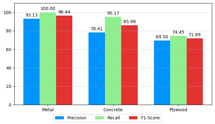
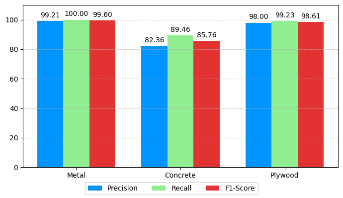
Figure 9: Detection metrics (precision, recall, F1-score) for each object and channel, evaluated after filtering.
Impact of Multi-Stage Filtering
Raw CIR-based peak detection yields large point clouds with significant noise and ghost detections. The proposed multistage approach reduces false reflections by up to two orders of magnitude, yielding spatially coherent obstacle clusters.
End-to-End Mapping
Final environment maps generated by the robot precisely localize all obstacles, achieving a median localization error of 8.5 cm. The CDF indicates 95% of errors are below 25.7 cm, demonstrating high SLAM suitability.
Figure 10: CDF of estimated position errors—demonstrating tight error distributions and sub-decimetric performance.
Environment-scale validation with four obstacles and nontrivial trajectories confirms practical viability.
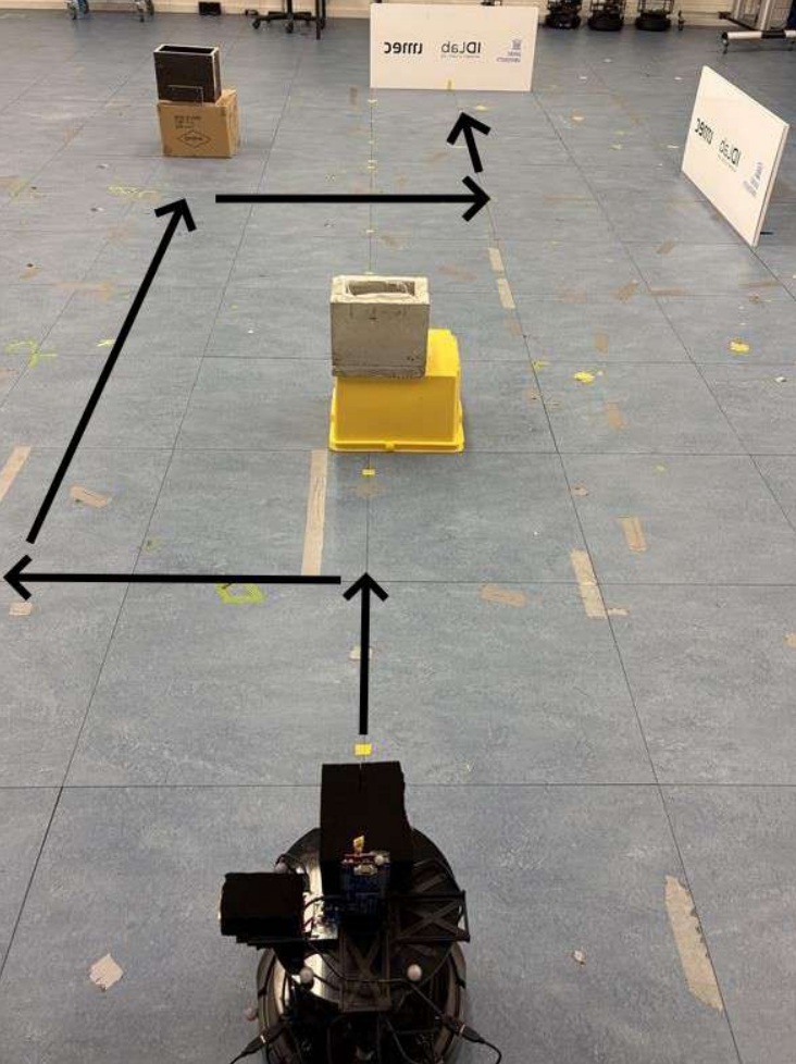
Figure 11: Lab setup with four obstacles and the robot trajectory during mapping.
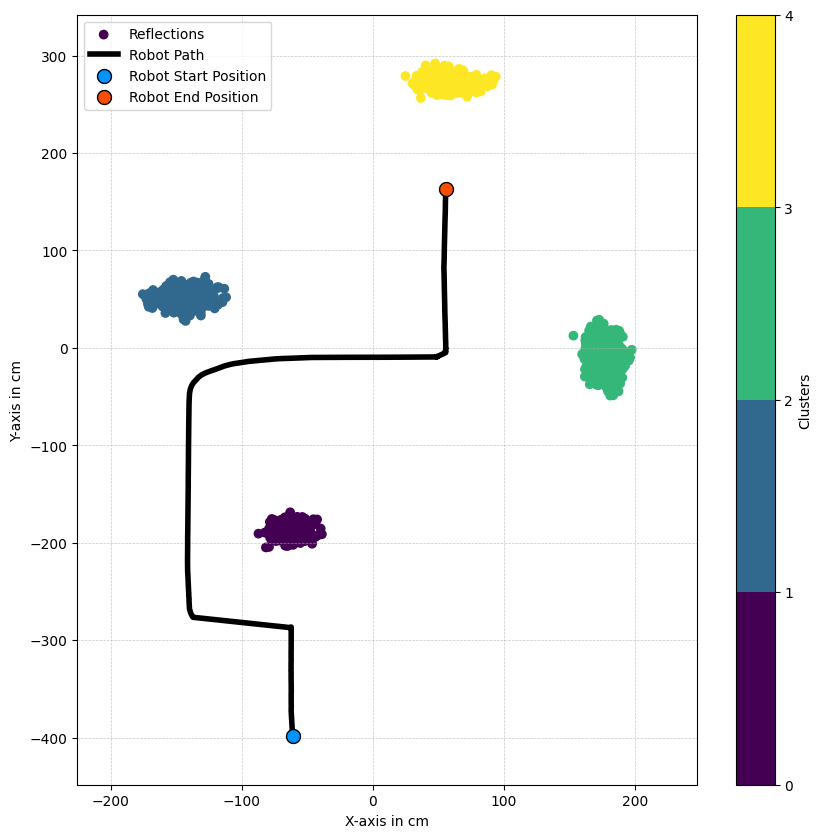
Figure 12: Final map with detected obstacles localized using the UWB pipeline.
Practical and Theoretical Implications
This work demonstrates low-cost, anchor-free UWB radar as a credible substitute for LiDAR/camera-based perception in environments degraded by visibility or RF clutter. The use of commodity IEEE 802.15.4 compliant hardware ensures immediate industrial applicability and joint S&C (sensing and communication) integration.
The pipeline's material-adaptive signal processing, real-time execution, and clustering step address core limitations of prior static-UWB or anchor-based SLAM solutions. Furthermore, integrating AoA via onboard PDoA allows mapping without spatially distributed infrastructure.
Key limitations identified are:
- Inability to detect objects closer than ~60 cm due to direct path dominance.
- Fixed rather than distance-adaptive filtering, which could be improved with context-aware thresholds.
Future Directions
Advancements can target:
- Improved antenna design or DSP to enable reliable near-field (<60 cm) detection.
- Implementation of adaptive, distance-aware filtering to further suppress false positives/negatives.
- Fusion with visual/LiDAR modalities for robust hybrid SLAM in heterogeneous environments.
- Application in UAVs, leveraging radar’s low weight and high penetration.
Conclusion
The presented infrastructure-free UWB radar SLAM pipeline reliably detects and localizes diverse objects—metallic and dielectric—in anchorless mobile robotic settings. It exhibits strong numerical accuracy, high F1-scores, and resilience to multipath and noise, paving the way for robust, low-cost robotic navigation in visibility-impaired industrial or dynamic environments. The approach provides a solid foundation for next-generation UWB-based SLAM and cross-modal sensing-communication platforms.